|
For reasons that we don't fully understand right now, when a Video Toaster fails to exit cleanly due to a crash or power outage, the settings for BOB are lost, and returned to factory defaults. |
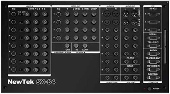
| Below is a close-up of BOB’s input connectors. The factory default is for the Toaster to have eight component inputs. Component connections use three cables: Y, U, and V (aka Y, R-Y, B-Y or Y, Pb, Pr, or Y, Cb, Cr). These variants of component labeling are pretty much all the same. |
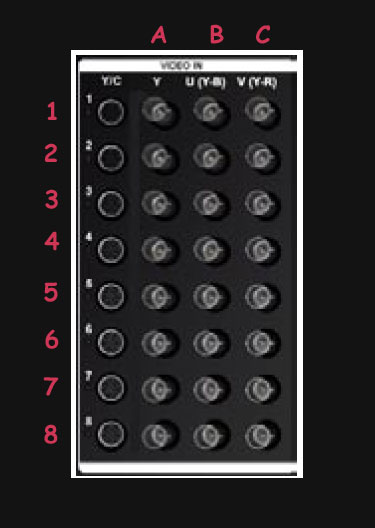
| BOB’s inputs can also be composite (one video wire) connections. Using the menus, the Toaster can be configured to have up to twenty-four (8 times 3 connectors) composite inputs, or any mixture of the above. The typical council installation uses from four to eight composite connections (the cameras) and two component connections (the DVD player and the Extron computer-to-video converter). The red numbers and letters don’t actually show on BOB. They are superimposed here for clarity. When composite inputs are used, the first three inputs are composite 1A, 1B, and 1C (the three connectors of the component 1 row). |
| In a six-camera installation, the six cameras connect to the first six connectors on BOB, and are as follows:
|
| Camera | Designation |
|
1 |
Composite 1a |
| 2 | Composite 1b |
| 3 | Composite 1c |
| 4 | Composite 2a |
| 5 | Composite 2b |
| 6 | Composite 2c |
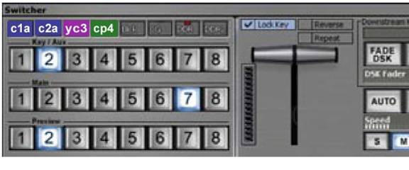
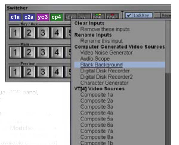
Looking at the labels above the busses, in this example, switcher input 1 is set to the composite 1a connector (c1a) Input 2 is c2a, three is the previously un-mentioned S-video connector on row three (yc3), and four is set to use all of row 4 on BOB as a component input (CP4) |
|
|
|
| The inputs to the switcher are selected by right-clicking on the label above the switcher buttons. The pop-up list starts with computer generated sources… black, DDR (digital disk recorder), Character Generator, etc. Under VT[4] Video sources are the twenty-four bnc connectors on the back. Composite 1a-2a-3a are the three connectors in row one, and so on. Below the first 24 listings are eight listings for the eight rows labeled cp1, cp2 thru cp8. A typical switcher will have the cameras assigned as the table above (camera 2 is Composite 1b for instance), and the two component sources (DVD and Extron) on the last two rows, cp7 and cp8. If you can easily see BOB in your particular installation (at the back of the computer), the Extron is usually wired with three identically coloured cables, and the DVD uses a cable with multi-colored cables, usually red, green, and blue. Usually. Assign other sources to the remaining buttons as necessary (DDR, CG, BLACK) Note the switcher may be set from eight to twenty-four inputs by right-clicking in a blank area and selecting skins. |
|
The Final Complication: After the buttons are assigned to the sources, they can be renamed. We generally use CAM1 CAM2, etc., DDR, CG, BLK, DVD and COMP (“computer”, for the Extron). This unfortunately renames the connectors in the list, so a configured switcher list looks like the column on the right (the left are the original names). Six Cameras are shown in this example. Usually, when the switcher loses its configuration, the list retains its names, so you just have to hunt for the sources by name on the list. We don’t know yet of any way to manually save these settings, but we are working on it. If you exit the Toaster program (VT4) normally, it saves its settings when it exits. It’s only at a crash or power outage that this is not successful, and then you have to rebuild. |