 |
|
 |
Digitizing is the process of taking continuously varying
things and turning them in to a bunch of numbers. This is done by
looking at them every so often, and noting their value on the scale.
Using the grid on the left, you will get:
8-9-10-9-8-5-2-0-1-4 In base two this is: 00001000-00001001-00001010-00001001-00001000- 00000101-00000010-00000001-00000100 In Roman Numerals: VIII- IX -X -IX -VIII- V -II -NULLA - I -IV It doesn't matter how we express the numbers, our sampling will be correct....
|
 |
Arrgh. Well, the IDEA is good, but the execution stinks. At the left is the waveform recreated from the numbers. It needs more samples in TIME, and more levels in SIZE. |
|
Not a bad picture |
Not enough samples in time |
Not enough levels |
| On the right is an Analog to Digital converter. The signal
at the image sensor is a varying analog signal that is digitized immediately.
From then on, it is processed as numbers until it gets to the display
device.
The output of the A to D converter is PARALLEL... each strip of eight ones and zeros exists at the same instant. Internally, equipment carries parallel signals on ribbon cables, but outside, we need the signals on ONE WIRE. |
 |
| So, we "serialize" 'em. In this example of 8 bits (binary digits), the serial output stream has to move 8 times as fast as the parallel input. |  |
| This presents us with our first challenge. How many zeros
are there in the space with the red arrow? The correct answer is "I
don't know".
We need a signal that marks off the position of each bit. |
| Here you go... a signal called "Clock" that
marks the position of each digit. Now you can count how many zeros are
in that row.
UH-OH! Now we need TWO wires for the two signals, or as Bart Simpson once said "Unless....." |
| I wish that I'd thought of this. It's clever. Each number position occupies the same amount of time. If it's a ONE, it changes state halfway through. If it's a ZERO, the voltage stays put for the entire clock period. The blue waveform is the SDI signal, the numbers above are the decoded bits. Notice that being up or down doesn't matter, as seen by the two adjacent zeros near the right. One is up, the other down, but both are zeros because they don't change state during their time-period. This is done so that there are never any mysterious long runs of "no change" as at the red arrow above. There you go, data and clock on one wire. You're welcome. |
|
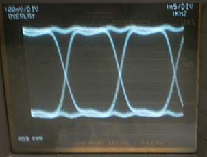
You will only ever see the SDI signal on a waveform monitor, which will overlap all of those pulses. That's OK because we can't make sense of them anyway, but there is an important attribute. |
To the left is a "One" transition, and above is a "Zero". We don't care about that. What we care about is the slope of the pulses. |
|
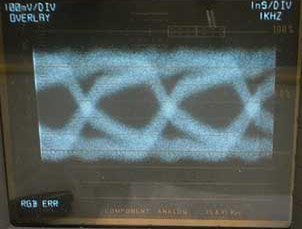
This is as clean as SDI gets. |
This is the signal after 300 feet of cable. |
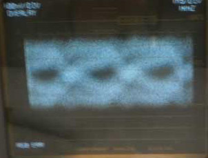
After 475 feet of cable is still recoverable. |
| Do studio producers need to know this? No, but anyone
doing remote work, hooking up trucks, or taking remote feeds should be
familiar with the eye. Analog pictures got smeary and snowy as the
signal degraded. Digital remains perfect until one more patch cord is
inserted, and there is NO picture! That right-hand eye is still
recoverable, but might not be after another short piece of cable.
$ $ $ $ $ $ $ $ The EYE display requires a lot of expensive analog circuitry. Don't expect to find eye on a waveform display that didn't cost around $10,000. |
![]()
![]()
|
|
|
|
|
|