 |
|
|
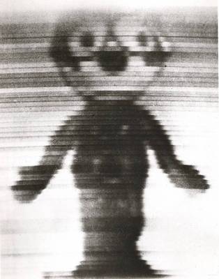
Felix the Cat transmitted 1928 |
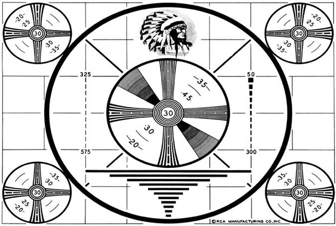
Television as we know it dates back to the 1930's and
'40's. You are often tempted to ask: “Why did they DO that?”
The answer usually goes back to the state of electronics 75 years ago when the standards were set. Compatibility has been the Blessing and the Curse of the North
American television system... A 1950 TV show will play perfectly on a modern set. Colour was added later, and plays OK on Monochrome sets. We chose 525 scan lines at 30 frames per second. Note that only 483 of those lines were visible. The others were blank and allowed for the system to reset itself from the bottom to the top.
|
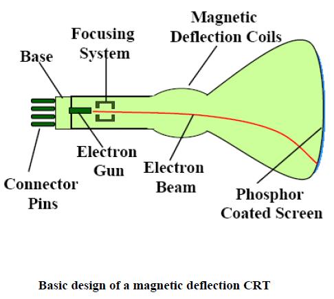
| The original display device for television was the Cathode
Ray Tube aka "Picture Tube" from 1928 to approximately 2010.
The CRT uses electro-magnetism to pull a beam of electrons in the desired scanning pattern. The beam hits a phosphor coating inside the front glass, which gives off light where the electrons hit... for a brief time. This "persistence" is chosen to last approximately the duration of one frame scan, but scanning 525 lines in 1/30 of a second still displayed some flicker. Clever thinking ensued... |
 |
 |
TA-DA! If we scan the tube with half of the lines, then
return to the top and fill in in-between lines, we still have our 525
lines, but now we are refreshing the tube 60 times per second with a
higher flicker rate for FREE!
However, interlace does pose a problem with fast sideways motion, and lately with bad computer math.
|
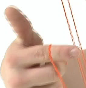
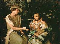
Full colour requires THREE primary colours to be present. |
Some early colour films used a two-color process. This picture has only red and green information. Lighter parts of the image have no colour, which makes the whole idea work... see white scarf. |
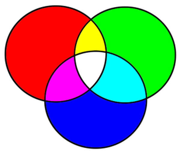 |
...And here they are! Yes, your art teacher lied to you.
The additive primaries are Red, Green,
and Blue. The Red, Blue, Yellow primaries
from grade three are SUBTRACTIVE primaries, valid when mixing paint and
ink... they mix by subtracting light until you are left with almost
black.
Red, Green, and Blue are ADDITIVE primaries used when adding coloured light together. Together, they make white. |
|
|
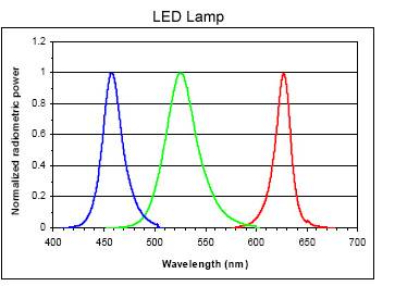
The human eye has sensors for Red, Green, and Blue, and any colour that you see is a blend of those colours. Each sensor has an area of overlap with its neighbour(s). The colour filters in the camera, and the filters/phospers in the display device are similar. There are two reasons to point this out... |
|
|
One, now you know why LED lighting sucks. The R, G, and B outputs are spikey in the spectrum, and some colours are rendered strangely under LED "White" light. |
|
|
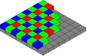
D'other reason..
This is the colour filter used on digital still cameras, cinema cameras, and cell phone cameras. It can be argued that it takes three pixels to make one full-colour pixel, but because of the response overlap, with lots of math, each pixel can be considered a full-colour pixel. |
| Most television studios use "Three-Chip"
cameras. The imaging chips are all the same, but view the scene through
a colour-splitting arrangement. The "Green" sensor sees any
colour that has some green in it, and so on for the other two sensors.
The outputs of these sensors form three video signals called
"Red", "Green", and "Blue", although in
reality they are just monochrome signals that show the brightness of
those colours.
To transmit "RGB" video requires three cables, or three television channels. SO... we're going to squeeze them into the space of ONE channel, AND we're going to do it in a way that millions of black and white TV's will not notice, and will still render a a good monochrome picture. |
.  |
|||||||||
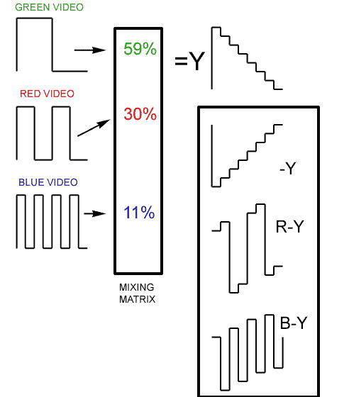 |
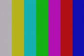
Don't panic.This is actually clever. The RGB video signals on the left will form full-field colour bars, as seen above. Compare the video waveforms to the bars... all four bars on the left have green, the three on the right have no green. The "red" video turns on and off every two bars, so white and yellow have red, cyan and green have no red, etc. Every other bar has blue /no blue and so on.Those three signals are added together to the proportions noted. Green gets the biggest percentage because we are most sensitive to green. Blue draws the short-stick for the opposite reason. This results in the signal noted as "Y", which is the main video signal broadcast. The monochrome TV sees this as bars stepping from white to black. Now, whip up some "minus-Y" ... just the negative of "Y", and add the red and blue channels to it. That gives you "R-Y" and "B-Y". "G-Y" is NOT NEEDED, since you can rebuild all three colour channels at the receiver with just Y, R-Y, and B-Y. Recap... We send colour with just the brightness of Y, and the two smaller colour difference components R-Y and B-Y Bonus... the colour-difference components are bi-polar. They are zero when there is no colour, and have positive and negative values depending on the colour.
|
|||||||||
|
|
|
|||||||||
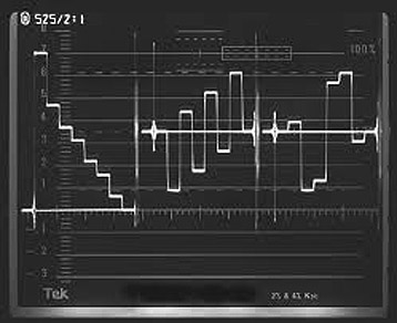
Bars Circa 1954In the NTSC analog system, the two colour components were modulated on to a fuzzy subcarrier, and a small "burst" of subcarrier was added to the signal to allow for proper decoding. It was an engineering miracle that served us well for 50 years... allowing the addition of colour to the existing video signal while keeping a compatible signal for those who did not have a colour receiver. IT COST US... the re-jigging of the signal meant reducing the scan rates buy 1000/1001 or so, and resulted in a frame rate of 29.97 instead of 30. This wasn't a problem until timecode was invented, and the new frame rate caused the time to be off by 3.6 seconds per hour. This is why we use dropframe timecode still to this day... so the time of our one hour show will read correctly at the end. |
Bars Circa 2005The bars are actually the same as the ones on the left, but the waveform display in Digital Video now shows Y, pB, and pR. What??? pB is essentially B-Y, and pR is R-Y. Note also that the order has changed from red/blue to blue/red. The two colour-difference components go by a few names. There are some subtle differences, but not so it matters to anyone but design engineers.
|
|||||||||
|
|
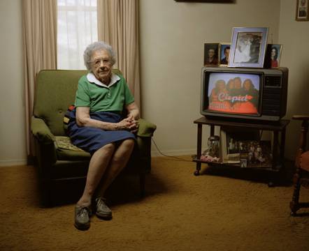
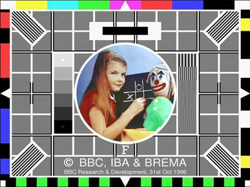
Blame GrandmaIn 2015, the colour subcarrier is gone, and we could have gone back to 30 frames per second. Sticking with the compatibility theme of North American television, we are still stuck with fractional frame rates... 29.97 instead of 30 and 23.98 instead of 24, and so on. It's all the fault of the woman on the left who refuses to give up her ancient TV. A converter box from the new digital ATSC broadcasts needs the fractional rates to get Grandma her subcarrier so that she can see her stories in colour. 29.97 Bah.
|
|||||||||
We nailed Grandpa, though..
Since day one, the NTSC system has specified black at 7.5% on the scale, as opposed to ZERO, which makes more sense. The reason was to give early TV sets a little safety in blanking the beam entirely during retrace periods. IT NEVER WORKED, and we were stuck with a loss of 7 percent of our dynamic range. By the dawn of digital, we all admitted the stupidity of this, and put black back to ZERO on the scale. |
 |
|||||||||
|
|
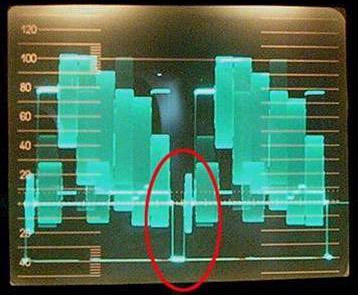
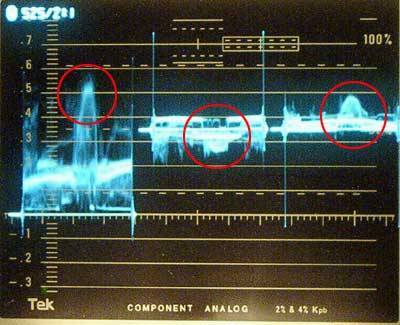
This is a talking-head shot on the newer waveform display.
It shows the Y signal, pB, and pR (those are the two colour-difference
components for those with a short memory).
The face is circled in each display. Note the pB (Blue difference) shows negative blue, and the pR (Red difference) has a positive value. There is no blue on the presenter's face. The big spikes are numbers in the signal that signify SAV and EAV... start and end of Active Video. That replaces the old sync pulses. The scale on this waveform is calibrated from 0= black to .7 = white. If you remember that the old one volt of video was displayed on a scale of 140 units (-40 sync to 100 units = white), and you know how to use a calculator, you can figure out where the .7 (actually .714) comes from. Most waveform monitors offer switch-able scales, and you can choose the old 0-100 scale. |
|
|
|
| The Betacam recording format was analog, but required
digital timebase processing for playback. In a way, it represents the
birthplace of PIXELS, which is a miss-spelled contraction of
Picture-Element.
Juggling several constraints, including the North American and European system differences, a rate 720 pixels per scan line was chosen. |
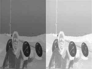
At the left is the Betacam "Y" channel... just a
black, white, and gray picture. The Betacam format was the first to
record the colour components separately in a clever way. R-Y and B-Y
were placed side by side and squeezed to half the width. The sampling
rate for both channels (Y and Colour) was nominally FOUR times
subcarrier (well, almost). Since the colour difference components were
squished to half, they were sampled at HALF the pixel rate of the Y
channel.
This sampling ratio is 4:2:2, and that's where THAT came from! |
![]()
![]()
|
|
|
|
|
|